Cat McClintock contributes to the Creo and Mathcad blogs for PTC. She has been a writer and editor for 15+ years, working for CAD, PDM, ERP, and CRM software companies. Prior to that, she edited science journals for an academic publisher and aligned optical assemblies for a medical device manufacturer. She holds degrees in Technical Journalism, Classics, and Electro-Optics. She loves talking to PTC customers and learning about the interesting work they're doing and the innovative ways they use the software.
Creo is 3D CAD software that helps you build better products faster. How? With tools that speed innovation, enhance collaboration, support design reuse, and replace assumptions with facts.
Creo 8 presents the logical next step for design engineers who want to take their design process up a level. Here’s what you’ll find in it:
Usability and Productivity Improvements
Let’s start with the “core productivity enhancements.” That is, the advances that make your everyday work easier or more convenient and generally don’t require any extensions. These are often the result of customer requests.
Workflow
In Creo 8, you’ll notice:
• A more modern datum display, with shaded planes and color coordinate systems.
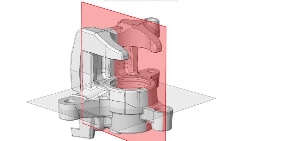
Image: A shaded datum display in Creo 8.
Plus, you can now:
• Detach multiple panels from the dashboard and display them at the same time.
• Take more control over the visibility of dimensions in Sketcher.
• Easily set transparency display for solid bodies, quilts, and tessellated geometry.
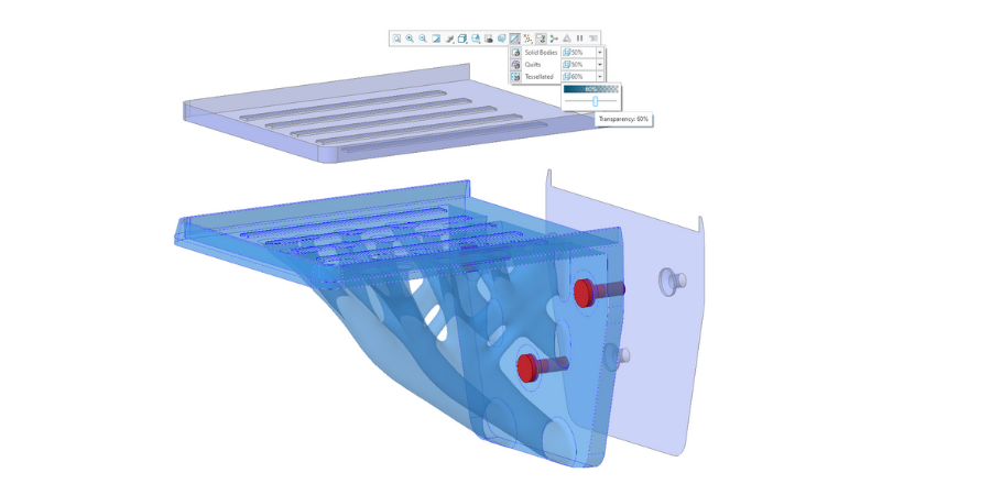
Image: Transparency Control in the in-graphics toolbar adjusts the transparency of bodies, quilts, and tessellated geometry.
Model tree
Document and communicate design intent more clearly in the model tree with new capabilities such as quilt nodes, custom groups, and side-by-side trees.
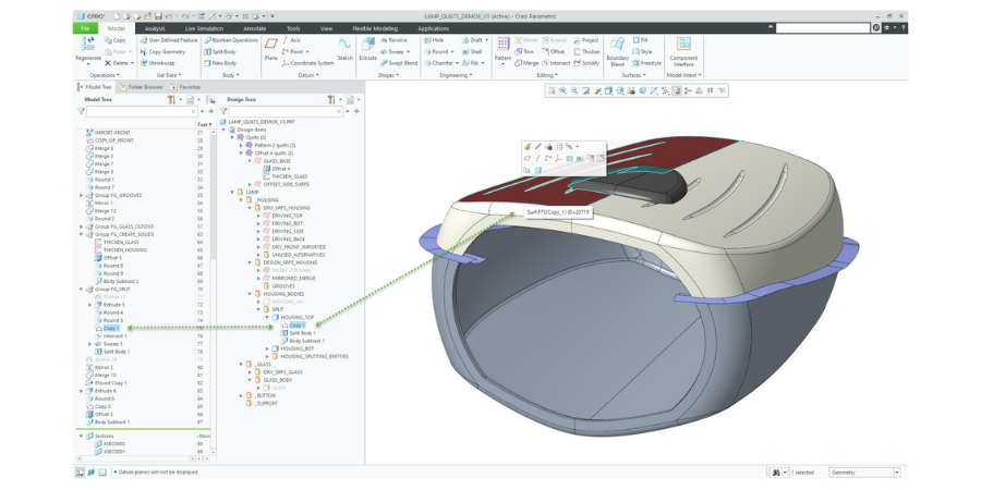
Image: New additions in the model tree include updates for quilts, bodies, and more.
Snapshots
Want a look back on your design’s early stages? Calculate and preview Snapshots of quilts and bodies with Show Snapshot. You can even see multiple previews together.
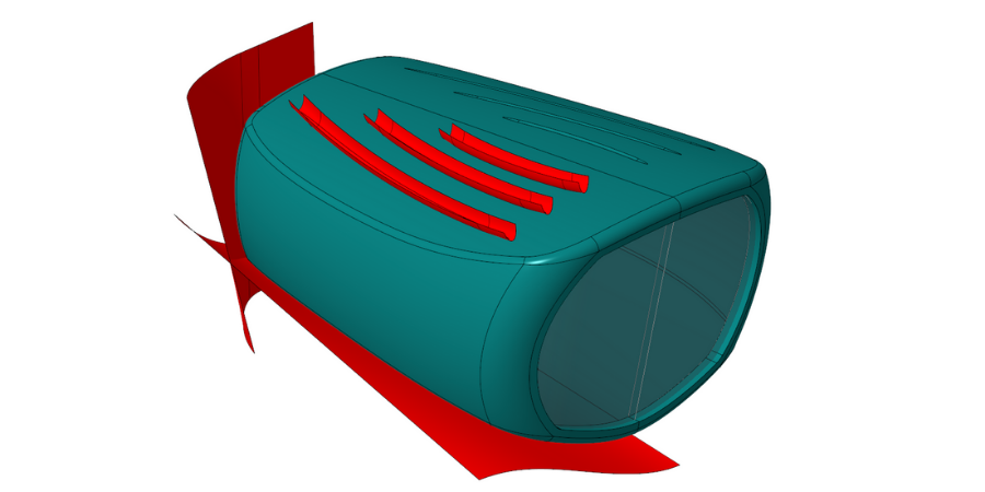
Image. Snapshot image
Hole features
Your hole features are easier to work with than ever with Creo 8. Now you’ll find:
• Enhanced standards support, including tapped, tapered holes and medium-fit options for metric clearance.
• Enriched thread-handling options.
• Lightweight representations for all hole types (helpful, for example, for speeding up models with many holes/hole patterns).
• Support for multi-hole features, with the new sketch-based placement option, including support for reference patterns based on the multi-hole feature.
Geodesic curves
Creating a curve between 2 points now has an extra option to ensure it represents the shortest distance over the surface between the 2 points. This can be helpful for cases like working with fabric in composite design or optimizing the layout and distribution of wiring and cabling.
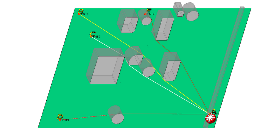
Image: Examples of geodesic curve option in use in Creo 8.
Sheetmetal
In Sheetmetal mode, you can create multiple flat walls at the same time. This includes creating miters for 3-bend corner situations and corner reliefs for inner and outer corners automatically. You’ll find the system smarter and faster when it comes to regeneration, too!
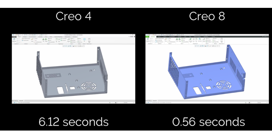
Image. Side-by-side comparison of a sheet metal part regenerating in Creo 4 and Creo 8.
Routed systems
In cabling and ECAD design, you can now:
• Create a branch tape cosmetic feature in cabling.
• Create stiff shrink cosmetic features in cabling.
• Import ECAD slots through IDX as ECAD cuts.
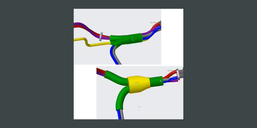
Image. Creo 8 includes new options for stiff and flexible heat shrinks.
Assemblies
Using purchased components in your assembly? With an inseparable assembly, you can include it in your model and do the following:
• Embed: Copy and embed the component into its owner assembly.
• Extract: Extract the component to a new standalone model, replacing the embedded component in the assembly.
• Make Inseparable: Embeds the lower level components into the selected assembly.
• Make Separable: Extract the embedded components from the selected assembly.
• Create embedded: creates a new embedded component in the assembly.
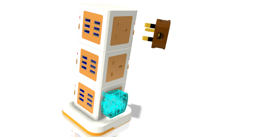
Image. You can now represent purchased assemblies as inseparable assemblies by embedding their (sub)components.
Render Studio
Use GPU mode to improve rendering quality and performance by using resources in your graphics card. Plus, you’ll find:
• Creo Render Studio now updated to the Keyshot 9.3 rendering engine.
• A new Denoise function in Render Studio speeds the rendering workflow.
• The PTC Hardware Check utility now evaluates for Creo Render Studio in GPU mode.

Image. Creo Hardware Check utility with Creo Render Studio option.
Model-Based Definition
Creo 8 adds new and powerful MBD and detailing tools to help you create rich CAD models that become the source authority for manufacturing, inspection, and your supply chain. In this release, you’ll find:
• Modernized symbols, including a customizable symbol gallery, semantic definitions, and enhanced contextual commands and workflows for symbol editing and placement.
• The GD&T Advisor Plus extension now includes support for assemblies.
• Annotation mismatch manager for greater transparency and user control over GD&T Advisor updates
• Advanced surface collection methods for standalone annotations.
• Improved sketching tools for drawing.
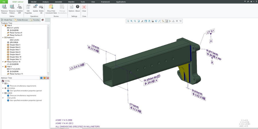
Image: GD&T Advisor for assemblies.
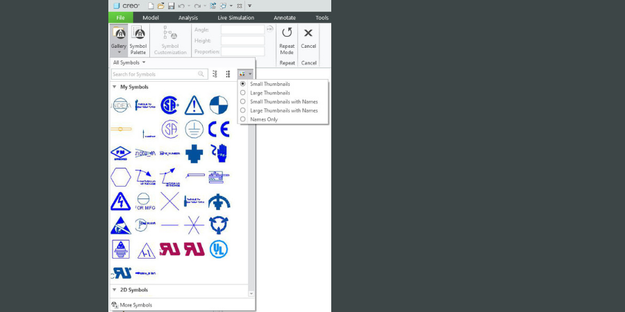
Image. Custom symbols in the symbol gallery.
Simulation and Generative Design
Creo’s generative design tools get even better with automatic envelope, draft-handling, and radius constraints. Enhancements to Creo Simulation Live provide support for steady-state flow analysis, for real-time simulation during the design process. And new Creo Ansys Simulation tools enable improved mesh and solver reset control for high-fidelity design validation. Look for:
• Generative design enhancements, including automatic envelope, draft handling, and radius constraint.
• Creo Simulation Live enhancements to support steady-state fluid flow and probe redefine.
• Creo Ansys Simulation with mesh reset control, automatically grabbing of license, solver setting reset, and large deflection control, for better simulation results and easier setup.
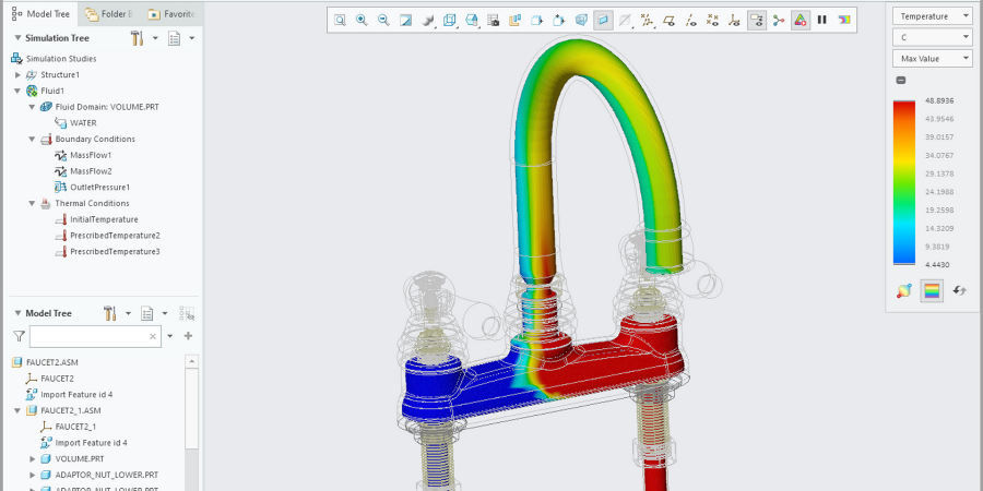
Image: Steady state fluid flow analysis in real time with Creo Simulation Live.
Additive and Subtractive Manufacturing
Optimize your designs for additive and traditional manufacturing with Creo 8.
With the new additive capabilities, you can use advanced lattice structures to minimize weight and apply variable lattice structures based on simulation results. Plus enhancements to the build-direction and tray setup help increase production speed and build quality.
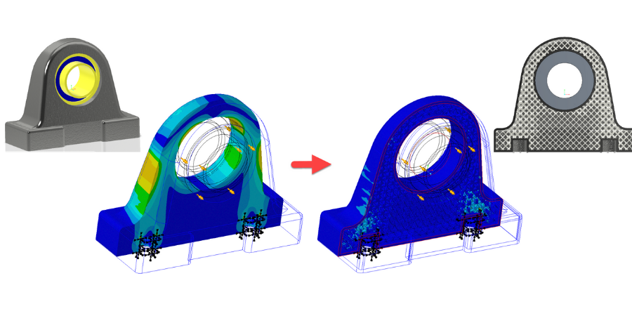
Image: Optimizing lattice structures with simulation.
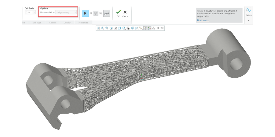
Image. Full geometry representation of a stochastic lattice structure in a part optimized for strength and weight.
For subtractive manufacturing, Creo 8 simplifies programming of 5-axis high speed milling toolpaths, resulting in less setup and machining time.
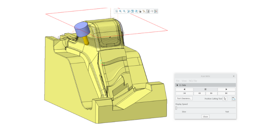
Image: 5-axis high-speed milling toolpaths in Creo 8.