Cat McClintock contributes to the Creo and Mathcad blogs for PTC. She has been a writer and editor for 15+ years, working for CAD, PDM, ERP, and CRM software companies. Prior to that, she edited science journals for an academic publisher and aligned optical assemblies for a medical device manufacturer. She holds degrees in Technical Journalism, Classics, and Electro-Optics. She loves talking to PTC customers and learning about the interesting work they're doing and the innovative ways they use the software.
With 3D printing (or more correctly, additive manufacturing), product developers have new options for prototyping, tooling, sourcing, and even producing parts. But with all these new options come new requirements for modeling.
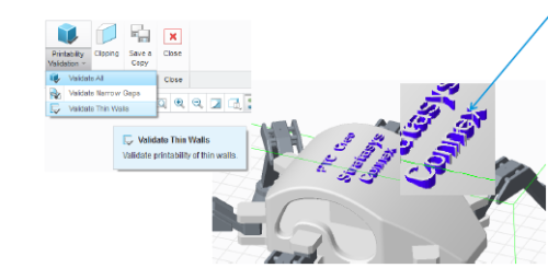
Creo now includes tools for validating models for 3D printing. In this case, a wall is unacceptably thin and probably won’t survive post processing steps once printed.
As engineers design products that will be manufactured via 3D printing, they need to know whether the model will survive the printing process without breaking—especially during steps like cleaning and polishing. They also need to know how the support material will interact with the design. For example, will support material fill cavities too small to clear away in post-processing?
The physical printer tray introduces some design constraints, too, limiting the size of the model that can be printed. And engineers might also want to set parameters like resolution, finish, and colors before saving the final STL file or sending it to the printer.
In the past, designers exported their models to various tools for optimization checks. But these days, you can use a single environment to design, optimize, prepare, and validate designs for 3D printing. Look for capabilities to:
- Connect and define settings for multiple printers.
- Identify printability problems within your design, such as narrow gaps and thin walls.
- Scale and position the model on the build platform for the most efficient manufacturing.
- View cross sections of your model so you can ensure no unexpected pockets exist.
- Assign materials, colors, and surface finish to the model.
- Calculate the required build time and support materials.
- Save the CAD data, translation, and position as one STL file.
If you're using Creo 3.0 or later, here’s how to get started:
- Create your model in Creo.
- Click File> Print > 3D Print to open the 3D Print This displays the 3D Print user interface and a new set of options. (Note that more options may be available when your selected printer as supported.)
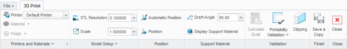
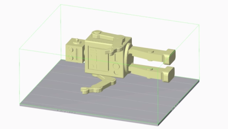
- Click Printer to select a printer, if the system isn’t already connected to one. Your model now appears in a tray, sized to match the physical printer.
- Click Position to translate and rotate the model on the tray using a 3D dragger. (If you’re using a supported Stratasys printer, the Automatic Position button will optimize your model’s position for you.)
- Click Display Support Material to see a representation of support material on the tray. This is an estimate only. The printer software determines the actual support material placement. But by seeing the support material, you can position your model to avoid situations where you don’t want critical surfaces touched during post-processing steps. For example, in areas not contacting support material, you’ll need less washing or polishing.

- Click Printability Validation to display gaps that are too narrow to print or walls so thin that they’re likely to break during production.
- Click Calculate Build to find out how much build and support material your model will need during printing.
- For sessions not connected to a supported printer, click Save a Copy to export your model, including its translation and rotation, to an STL file.
- For sessions that are connected to a supported printer, you’ll have the option to click Print. That starts the 3D printing process directly.
These are just a few of the new features available for optimizing design for additive manufacturing in Creo 3.0 or later. Feel free to explore the others with your models, or see this comprehensive list of functions.
Important Update
You're all caught up on Creo 3.0. But there are many more fascinating new features for anyone serious about leveraging the unique properties of additive manufacturing (think lattice structures) in their designs. Check out what's new in Creo 6.0.