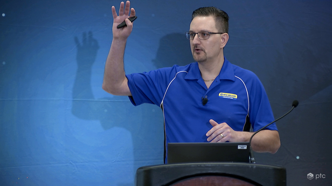
The Journey to Implement Creo Welding Applications for MBE
Download the slides here.
00:00 Welcome to LiveWorx. My name is Roger Mast. We're here to talk about Caer Industrial's journey to implement the welding application. And so first of all, we'll just highlight the key points of what we want to go over today. And that way, in case you know, you didn't know why you were here, if you misread the title of the presentation, you thought it said wielding and not welding. It's not about sword fighting or Lord of the Rings or anything like that.
00:30 We're going to talk about the welding application, which is modeling the welds, what all is involved with that? Our industrial methodology go into a little bit of details about that and our implementation challenges till date. So audience participation as well. So in case again, if this is not why you what you thought you were coming for, you can go ahead and step out now. They won't point the camera at you to see you leaving or anything like that.
01:02 But audience participation. So just so you can get in the mood of things. How many people are here to learn something today? Great. Everybody's hand went up. I didn't have to scold anybody or anything like that. So great. This is a short session this year there are only 30 minutes long, so we've got to keep it moving again. My name is Roger Mast, also known as that Weld guy or Mister Weld. People have heard me talking about these topics over the years and so
01:33 I will answer that. If you go ahead and say that I've been around for a long time at Industrial, 25 years. I'm from New Holland, Pennsylvania. I've done a lot of things over the years before taking this admin role. I've got some patents, for example. In fact, I've been coming to these conferences since 2006, so I'm getting old. Like some of you I can see out there have been around a long time to.
02:03 If you're not familiar with Industrial, we are a company that makes construction and agriculture equipment. You might not be familiar with industrial, but I'm sporting the new Holland brand today. We also have Case and many other brands that you can see on the screen. We're a big company, 40,000 employees, $23.6 billion in revenue last year, 43 plants, 40 R&D centers. Our new CEO came in a couple of years ago,
02:37 Scott Wein from Polaris. And he's implemented a new purpose, breaking new ground, which centers on innovation, sustainability and productivity. So we're a very customer driven company. All right. Now that we got all the introductions out of the way, I want to ask a question just to get a sense of where my audience is. I'm going to ask the question, What is your experience with the welding application? It's either going to be expert, novice or newbie. It's okay to be a newbie.
03:09 There is no shame in that. So if you would say, I'm an expert, where are my experts? Okay, novice. You know a little bit about it. Okay. And where my newbies because I'm really looking. All right. That's what I like to see people that are here to learn something new. All right. So let's jump right into it. I won't go too fast through the welding application details because I want to make sure you understand what this tool can do. So first of all, this is an application inside Creo.
03:40 You enable this application and once it's enabled, you can go ahead and create some features in your model. You can see the features there on the screen. I don't think my pointer shows on there. So let me do here. All righty. So you got your features in the model tree like so. Once you've got your features, you also have symbols. So these symbols can be used on your 2D drawings, on your 3D drawings,
04:11 whatever the case may be, whatever you happen to be doing. And once you've got those features inside your model, you can get reports on that information. You can do mass properties depending on the type of weld that you create. Now, one thing to point out, just so that there's no confusion, these if you look down here. So that's the geometry . And these are my parts. So unlike in the real world, when you do welding,
04:41 we're not fuzing any material together here. The original sheet metal parts, for example, are going to remain unchanged in your model. So nothing's actually happening from a properties characteristic inside that model. All right. Standards and types. So again, real quick, S and ISO are supported. I got a couple of the standard versions on the screen there. I will say they're limited support. It's not fully supported.
05:12 There is gaps in the process and we'll highlight what some of those are as we go along. As far as the elementary weld types, you can see fillet welds, bought welds, plug welds and spot welds. Now I pointed out here, I only put one type of butt weld here. There's actually a lot of different butt welds you can create, but just for simplicity, just so that you understand, that's not the only type that you can create. The geometry representation.
05:43 This is important that you understand there's three different kinds of geometry that you can create. The first one is lightweight wells. This is a 1D curve that goes inside the model. This is the fastest, but it has the least amount of functionality. So your mass properties, for example, are not going to be easily generated. You can't do interference checks because there's nothing physically. Their surface is what we can see here.
06:14 We've got this surface and that's it's just like a sheet that's laying on top of the models. As you can see there, the performance is pretty good. This is probably what most companies have been using up until now. You see some benefits in terms of interference. Checking can be possible. And then the third type is the solid. And notice that each of these has a unique icon in the model tree.
06:44 And of course, this solid and the the curved one or the lightweight one up here, you know, it's nice that they made two different blues because. I'm sure you all in the back can see that those are different colors. Anyway, little, little dig there. So the solid is good in terms of its capabilities. So you get automatic mass properties are calculated, you have interference clearance checks that you can do in a robust way,
07:15 but they are the slowest. So you just have to understand there is a price that you'll pay from a regeneration standpoint when you're using those. Another thing to point out, if you're doing big welds on construction equipment, for example, and you want to do material removals post Weld, the Solid will show that geometry removal process. None of the other ones will. Okay. Benefits again real quick because we do only have a short time today.
07:49 You can confirm the type of well that you have. So from a presence point of view, you can see them. You have mass properties, clearances, interference checks. Again, depending on the type of weld that you choose, you may not have all these benefits Being able to communicate that welding information downstream without a drawing is the main reason that our company really started down this path. Our fire and simulation group wanted to be able to get that information as quickly
08:20 as possible before you ever had a drawing. And so this can do that for you. Also the ability to have that symbol relate on the drawing your 2D drawing today. If you're not model based definition, having that relationship to the model and knowing that you've got all your welds shown on that drawing is also an important benefit that you can achieve through this. Now a couple of other details. Not on my slides so well. Materials you can define process information, edge treatments,
08:56 parameters. So there's parametric information on these features both coming from the out of the box, if you will, solution, but you can also create custom parameters for your Weld features as well. All right. Poll question. Is your company modeling the welds? Again, three choices the majority of the time. Sometimes or never. So how many companies people here representing are modeling the welds all
09:29 the time? A few. Good. How about sometimes? More. And how about none? Okay so the non and the sometimes is pretty similar. So of those who said yes, the majority of your welds are made in either light surface or solid. So who's using the lightweight? Couple about the surface. And then solid.
10:00 That's more than I expected, to be honest. That's probably the biggest amount of anybody . So. Okay, good. Interesting. So we'll move now to industrials journey. So this is my journey in many ways, because for me, this started back in 2014 when we started to evaluate Creo two. And at that time, we really like I said, we wanted to be able to eliminate our drawing in the process when working with our FCA group.
10:32 We wanted to be able to get away from our own custom welding symbols, do more model based definition things. So that's really how it started. If you saw my presentation maybe three years ago, I really went into a lot more detail than what I will now. But at that point, you know, the tool was very immature for my point of view and we really had no intention to go any further with it at that point. But we did have business people and engineering saying, Hey,
11:02 we wanted to use it. So before we had to herd the cats, if you will, we decided to implement a process to try and formalize what it is that they're doing. And we quickly ran into some problems, which we'll talk about in a couple of slides from now. But we'll just fast forward to the eventual organic growth that we started to see. After implementing this process, we started to do some of our own customizations map keys.
11:32 UDFs to try to improve the efficiency of our usage of the tool and really through Creo four was what that presentation a few years ago was about. And I really want to talk today about what happened between then and now with Creo eight and our implementation of the Solid Weld. So a little bit of the background because I know we have some new people here that didn't see that so that you understand what the initial challenge was for us was the fact that these welding symbols,
12:05 as you can or features, as you can see in here, are on the assembly level. Why does that a problem? It's a problem for us because we use Teamcenter and GE for our lightweight visualization. And as you can see over here in the GE representation, there's no weld geometry shown, and that's because we only publish parts in a JT file and not on the assembly level. So our solution for that was to implement a weld part.
12:37 So if you look at that right there, think of this as a skeleton model that you're putting in each and every Weld assembly. That will be the container for all of your Weld features. And as a result we are able to publish the JT for this Weld part and have all of our welds shown inside there. So this is our unique approach and you're going to see as we go along, there's definitely a number of benefits to that. So first of all, for us, lightweight visualization.
13:08 Two thumbs up, excited about that and you're probably going, well, that's not a problem for us. So what? Well, how about this one? Easy filtering by simplified reps. If you're modeling on the assembly level, can you make a simplified rep that excludes all those Weld features? The answer is no. I can do that really easy with a rule based simplified rap that's looking for that underscore weld name. And every level doesn't matter what it is, just like that is gone.
13:40 So any performance problems that I want to avoid or regeneration issues just like that, it's done on the assembly level. You can't do that. I also like the ability to independently control that file in my database the same as I would for a skeleton. And also from a model organization point of view, I've never really liked them on the assembly level because I modeled some components. I got my components in there, made some welds.
14:10 Now I add more components, more welds, and I've got this mess of a model tree with just mixed stuff up all over the place. And this really eliminates that whole issue as well. So that's again the background of our methodology and why we implemented it. And so if we look now at our Creo evaluation, just I'll point out a couple of the enhancements in case you're not familiar with those like the rest of the user interface, you can see between Creo four and Creo eight,
14:44 we have these nice labels now added. So a lot easier to use. All of the Weld schemes and this is ISO because we use ISO to be clear. They're now selectable immediately from the dashboard instead of this dropdown list. And an interesting twist of irony, the plug weld, they did just the opposite and Creo for they were on the user interface then they now put them in a dropdown list. So I don't quite understand the logic of that,
15:15 but I'm sure somebody at PTC can answer that. If you go to their booth intermittent. Well this was a nice enhancement as well, putting this into its own little group down here and I have a page on that later where we'll look at all those benefits and then the location immediately opens up like many of the other features in Creo eight. So when you're going to make your placement, you can see immediately what you have to do in order to create that feature.
15:48 Next up is the improved solid welds. This is a game changer right here because for us this was a blocking point in Creo for where the representation is. You can see around corners, for example, was not showing correctly. And for the solids, we don't want to have that confusion with the surface. It was going nicely around the corner and now the solid is doing it as well. Well, preferences is another nice enhancement. You're now able to choose the schema that you want. Pray.
16:21 Previously it was always the A We never liked that. We always use the Z by default, the intermittent. Well, this was another real nice enhancement from an end user perspective. You can clearly now see your spacing over here how it's going to end, whether it's with a gap or with a weld. It's clearly spelled out in Creo four. It was very vague, to say the least, as to what you were going to get at the end of the story.
16:52 Another enhancement is you're now able to establish a pitch by a particular value. So I can type in my spacing, my distance and my number, and it will create them from one side or the other. Previously, with the automatic, it would always space those across the entire distance of that trajectory. And finally for the staggered intermittent, well, they fixed this annoying behavior. It may be hard to see in the back, but in Creo four, this was always the same number on the top and the bottom.
17:24 But if you look down here, there's actually only supposed to be two on this side and one on the opposite. Now, correctly shown in Creo eight and before even in Creo four, even though the symbol was wrong, the mask properties were wrong too. It was always adding one more weld to that feature. And then what was actually there. Another nice enhancement for us in the ISO world was unequal leg length that was available for us but not ISO semantic references for your weld features.
17:56 So if me this was another nice enhancement bug fixes. These are all bug fixes around symbols so that really because of the bugs we saw in Creo for limited the amount of people that wanted to use the symbols on the drawing. Those are now corrected. Now, if we look at the not so good, the not so good is the 22 cases that I had to open around the welding application. It's a pretty big number. 15 of those issues, I'm happy to say, are resolved.
18:27 So if you're using Creo 807 or newer, you're welcome, because we put in a lot of effort to try and get these things fixed. The other cases is the dreaded closed as known limitations or working as designed or prospect. That's the answer we all love to hear when we open up our cases, don't we? But that is what it is. And we'll look at some of those in a little bit.
18:57 The one thing I will point out, if you're coming from the world of surfaces and you want to compare that behavior with the solids, you will find differences. And the main reason is the solid weld isn't really a feature, it's an embedded component. And because of that, this was PTC first effort in Multibody technology. Those are actually parts, even though they look like features. And you'll see some illustrations of that in some of my next slides where it is clearly,
19:29 clearly known. So the decisions that we came to as the result of this project is we selected 807. We've been live with that for about one month now. I was hoping when I put in this presentation that we would have more time experience to share with you. But I can say from all the years of Major Creo updates that I've done to Creo eight was the smoothest upgrade we've ever had. No major issues. No major complaints.
19:59 In fact, we had a user meeting with guys and girls from across the globe. 25 some people there. Not a single person could give me a bad thing that they didn't like about Creo eight So I was really happy about that. On the flip side of that was from a project point of view, it was the most difficult upgrade project that we ever did with delays and bugs and problems. But fortunately we found and fixed those before it got into production . So we're happy with that.
20:31 From an engineering services point of view. We've changed our process now from a welding point of view to recommended. Previously it was optional, but we now recommend all of our engineers model the welds and we've adopted the solid weld as the default behavior. But we do allow people to configure their environment back if they need to. All right, here's a poll question. So what version of Creo?
21:02 So let's say earlier than seven. Who's using something less than seven? Okay. Who is on seven? That looks like a majority. Newer than seven. Well, no mix there. A lot of people. And as anybody, I'll just ask who's on nine? Anybody on nine. Okay. So most of them were eight. All right. So if you're on 8 or 9. What's your experience? And you're using the welding application, let's say, favorable or negative.
21:34 So who is happy about their experience in Creo eight with the welding? A few who was not happy with it? Well, nobody. Well, maybe one, so that's good. So that should tell you guys that are on something earlier than eight that there's hope of some good things like I'm showing you all here. All right. Implementation challenges. Surface to solid conversion is the first use case we'll look at.
22:05 Now, this is let's look in particular at the butt welds. And when you convert those using the PTC tools, that looks like a good feature, right? Nobody would tell me that that feature looks like it's in a failed situation. But if you add a definition on that feature, you will find it is in a failed situation because it's missing this reference. If you do the conversion in the context of the feature, so add a definition switch,
22:36 click solid, then you don't have this problem. But in the right mouse button, if you click convert, you will get this problem. Again, this is that dreaded works to spec thing that I talked about earlier. Excessive regeneration and poor performance during the conversion. If you have a couple of hundred welds in that assembly, I will tell you it's going to take 30 to 60 minutes probably to convert those to solids.
23:08 At least that's the experience that we saw. And this is what I meant earlier about embedded components. If you can see that in the back, maybe you can. It says Weld component, blah, blah, blah with an ID number. This is how, you know, it's embedded component. When you erase not displayed, after you close your model, you will see model instances for each of these weld features. So if you have hundreds of welds in there, there's actually hundreds of other components in session that you didn't know were there. Now for us, we found some relief by some internal customizations.
23:44 So we have been able to overcome using our tools this problem as well as improving the performance of this conversion process. But unfortunately for you, that's not going to help you. So that's why you want to get on PTC a little bit to try and improve that other software limitations. And some of you have seen this before. Complex geometry is very difficult to achieve or impossible to achieve. You can't wrap around the corners. You can't do nice extensions.
24:17 You can't blend as you would in the real world between a couple of different types. So as you can see, this does not look like that. And until this looks like that, we are blocked. From a true MBT point of view, we were some of you were probably on the first floor during the last session. Schiff We can do all this stuff. If you can't make the model that doesn't do you any good to get a. Schiff. Okay. If you're doing simple stuff, great. Have at it.
24:48 If you're doing this, you have a problem. Other software limitations. If you use any of these weld types that I'm showing on the screen, you're going to have a problem because they're not there. Another blocking point. And now we'll run through a bunch of them. So the wildlife in your symbol doesn't really follow the standard. We've overcome that by changing our drawing standards to follow what PTC is doing, not what ISO is doing.
25:20 If you do want to get an XML export from Creo nine, it's not probably going to be in a format that you want. This Mqf is the one that we were hoping they'd give us. Not yet. If you want to edit the leader attachments of the symbols in your 2D drawing, you can't without breaking the relationship to the corresponding feature in the 3D model. So you have to always go to the 3D model. You cannot independently control your solid weld visualization and your symbol.
25:54 If you put that stuff on a layer and you turn off your solid weld display, the symbols go away too. Now we figured a workaround from that. If you put the weld part on a layer, you can hide that and still show the symbol. But you're not following our process so you won't be able to do this. Sorry for that. So again, talk to PTC cannot combine similar welds that are defined as double sided.
26:24 You can't control all the Weld preferences, for example, your plug slot weld scheme, your tangent propagation. So there's still some limitations there. It's cumbersome to edit the joints out of your fillet weld with a butt weld. You've got nice drag handles, you have dimensions that you can quickly change. Not so much with the fillet weld spot welds don't create a usable axis or point at the end of the story. And the Weld reporting is poor.
26:56 Again, this is we've worked around this by writing our own tool kit solutions to extract the information that we want. Okay. So at the end of the day, there are many benefits to modeling the welds. Hopefully that last little bit doesn't discourage you from moving forward because I think there is a lot of benefit. It is possible. It is going to be hard work. You might have to work with your drawing standards. People, if they're willing to compromise a little bit, you can probably get something done.
27:26 But again, you have to stay committed if you really want to get it done. MBA is not fully supported yet, unfortunately . So what can we do? Well, we can get involved. So I am the chairperson currently of a Weld working group co-chaired with PTC. I have the link on the slide there please. It's a private group, so just go on there, request to join and I'll approve you or one of the other managers of that site will approve you.
27:56 And that brings me to the end and any questions that you might have I'm happy to answer in the couple of minutes that we have left. I haven't used the module itself yet, but if I do, is it required that all the models and the assembly all have the exact same accuracy setting? No, there's not a requirement from an accuracy point of view that we've encountered for sure. I would say if possible, you want to go to absolute.
28:26 You don't want to be using relative anymore. But we haven't encountered any issue with the way our process is done. But again, ours are being created in the context of a part. So that's kind of controlling the accuracy there. And we're not having them on the assembly level, but so far so good for as long as we've been doing it. Okay. And you also showed that it doesn't really support the MDM solution, but have you been setting out step files and how well do they translate out the information and import back in?
28:56 So for step files, yeah, I mean, I'm sure like many people, there are limitations to step files at this point. We're not using that as a part of any of our main process. So our fire team, for example, they're taking the Creo models out and they are extracting information that way and not using the neutral format so much.