Katelyn Stevens, Senior Content Marketing Specialist, has worked for PTC University since 2007. A graduate of Mary Washington College in Fredericksburg, VA, she has her bachelor’s degree in English Literature with a concentration in Linguistics. Katelyn worked as a professional editor and manager for more than 10 years before switching over to content marketing. She is a regular contributor to the PTC University blog spot and writes in depth interviews and articles on emerging technologies in the education space. In addition, she manages PTC University’s social media platforms and creates original content as a thought leader in the industry. Katelyn currently resides on the south shore of Massachusetts with her husband, two children, and golden retriever.
A 2D drawing view is a representation of a 3D CAD part or assembly that is placed on a drawing sheet. A drawing view represents the shape of the object when viewed from various standard directions, such as front, top, side, and so on.
Most designers and engineers already know that. What you may not know is how much more you can do with your drawings, with just a little bit of guidance.
In a recent presentation, “Creating and Modifying 2D Drawing Views,” PTC University and Creo Curriculum Manager, Matt Huybrecht, explained multiple view types, including detailed views, cross hatching options, and more.
Check out these five key takeaways:
1. The Basic Drawing View Types
There are various views you can add to a drawing, including, but not limited to:
- General View – When you create a drawing, the first view added to a drawing is a general view. A general view is usually the first of a series of views to be created.
- Projection View – A Projection view is an orthographic projection of another view's geometry along a horizontal or vertical direction from the parent view. The orientation of the projection view is always 90 degrees from the parent view, and its scale is dependent on the parent view.
- Auxiliary View – An Auxiliary view is a special type of projection view. Instead of being projected orthogonal, the auxiliary view is projected perpendicular to a selected planar reference (a datum plane) or projected along the direction of an axis.
- Detailed View – A detailed view is an enlarged view of any existing model view showed in a smaller portion.
- Cross-Section View – A cross-sectional view is a cut-away portion of a part or an assembly in order to show its interior structure or hidden components.
2. The Cross-Section View Types
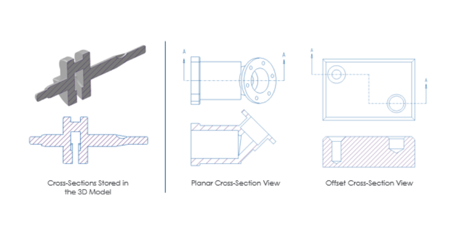
A cross-sectional view is a cut-away portion of a part or an assembly to show its interior structure or hidden components. You can display and configure many different types of cross-section views in drawings. There are two main types of cross-section views that you can display in drawings:
- 2D cross-section views – You can display these cross sections in 2D views. They can either be planar cross sections where the cross section cutting line follows a datum plane or planar surface, or they can be offset cross sections where you sketch a cutting line through the solid model.
- 3D cross-section views – You can display these cross sections in 3D views. You can create them as 3D cross sections within parts or assemblies, and you can control the display of their cross-hatching within drawing views.
3. Adding Detailed Views
A detailed view is an enlarged view of any existing model view. When you create a detailed view, a reference note and border are added to the parent view. You must define the following when creating a detailed view:
- Spline – Select a center point in an existing drawing view that you want to enlarge in the detailed view. You must then sketch a spline around the area of the view that you want enlarged in the resulting detailed view. You do not have to be concerned about sketching a perfect shape because the spline is automatically converted into a boundary shape.
- Location – Select a location on the drawing where the resulting detailed view is to be placed. Similar to other views, you can always move the drawing view at a later time.
4. Editing Visible View Areas
You can edit a view so that only portions of the view are visible. This is useful if the design model is an awkward shape and standard views take up too much space on a drawing. There are a number of different view area options available, including the following:
- Half View – Removes a portion of the model from the view on either side of a selected cutting plane.
- Partial View – Displays a portion of the model in a view within a closed boundary. Model geometry outside the closed boundary is not displayed.
- Broken View – Removes a portion of the model from between two or more selected points and closes the remaining two portions together within a specified distance. You can break horizontally, vertically, or both, and use various graphic border styles for the breaks.
- Z-direction clipping – You can specify a plane or reference on the model that is parallel to the screen and exclude all graphics behind it.
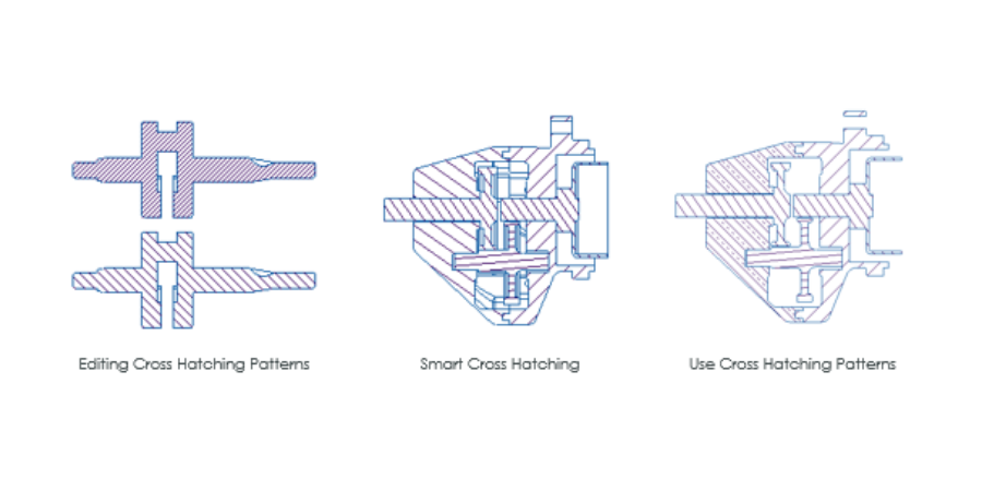
5. Modifying Your Cross-Hatching Display
- Cross-sectioned components are represented by different cross hatching styles. You can modify the cross-hatching styles displayed in part and assembly cross-section views by editing a number of attributes for cross hatch patterns, including:
- Spacing – You can half or double the cross-hatching line spacing.
- Angle – You can edit the angle by selecting a predefined angle or by specifying a different angle.
For even more insights, remember to follow PTC University on LinkedIn and Instagram @PTC_University.