[Editor’s note. We don’t know whether the Millennium Falcon was created using top-down design, but it should have been. Here's why.]
Imagine you’re a chief engineer at the Corellian Engineering Corporation and you’ve just received a new assignment. You are to design a successor to the YT-1000 transport ship, and your customers want a larger vehicle with more modular options.
You realize a few things about the assignment:
- You’ll be able to reuse a lot of existing components.
- You have to design for modularity.
- This is an incredibly complex design with numerous interdependencies between systems.
Here’s why you would need a top-down design methodology to get the right balance of creativity, control, and speed.
Start with the Engineering Notebook
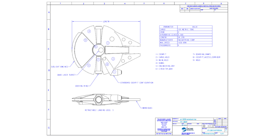
Notebooks are a great way to use rough sketches, dimensions, parameters, tables, and notes to capture design intent and lay out the most important information that affects multiple systems and components.
We can also use them to document requirements, to source control data, and for any other information that we want to capture and control at the top level.
Here is our initial Notebook for the YT-1300F in Creo Parametric:
Define the Product Structure
Let’s create our top-level assembly, subassemblies, subassemblies within subassemblies, and individual parts. At this point, we aren’t building any geometry. We are simply laying out our product structure so we can figure out what components we need to make, buy, and manage. We can also leverage existing models that we want to reuse. By setting up our product structure early, we’ll be able to farm out design work among our team members and partners.
Here you can see a sample initial product structure for our freighter. Note that we’re also using configurable products and configurable modules since our vehicle will be modular and our customers can configure the cockpit, weapons, and engines.
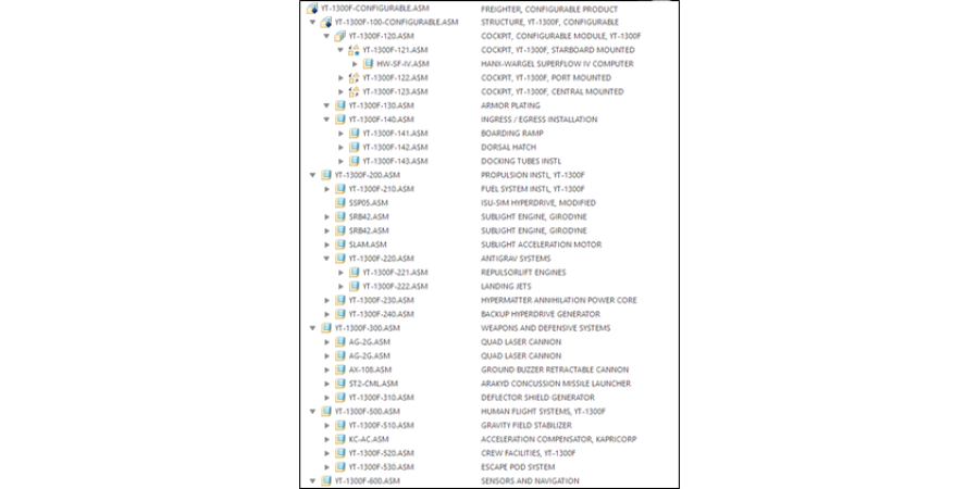
Initial product structure for the ship in Creo Parametric
Create Skeletons
We use special part models called skeletons to capture important geometry that affects multiple components. For example, here is a skeleton we use to define the outer mold line (OML) of the vehicle:
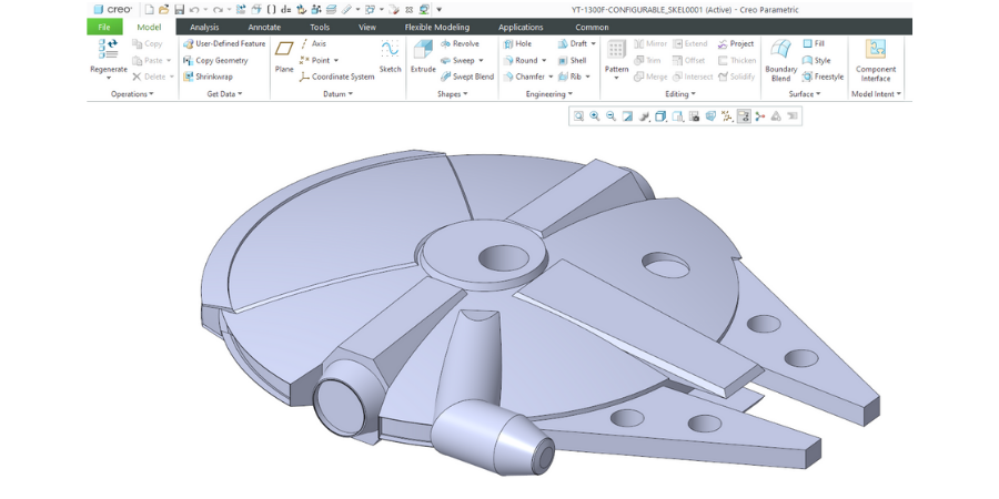
Image source: Joshua Maruska, GrabCAD.com
Skeletons can also be used to define structures, interfaces, space claims, mechanisms (like quad laser turrets and landing gear), and envelopes for commercial off-the-shelf (COTS) components like our hyperdrive and sublight engines. Skeletons would also be used for routing the cable harnesses and piping for the hydraulics, fuel, water, air, and other systems. We might even have multiple skeletons at various levels to keep our models organized.
Communicate Design Information
Now that our notebook contains our most important parameters, and our skeleton model consolidates critical geometry, it’s time to share that information with our parts and assemblies.
By declaring our models to the notebook, all the notebook parameters are available to be used to drive feature dimensions. We write relations to drive feature dimensions from the notebook parameters.
We use data-sharing features like Copy Geometry, Shrinkwrap, Merge, Inheritance, and Publish Geometry to communicate geometry from higher-level skeletons to lower-level skeletons and to individual parts.
Populate Your Model
With our distributed information, we can perform detailed design to create the necessary features and geometry in our parts. We can also continue placing any other components, like parts we’re reusing from earlier product lines, other COTS parts, and hardware (fasteners).
By using top-down design tools like notebooks, skeletons, and data-sharing features, we can design and control complex products. Now you’ve got a vehicle that a scruffy-looking nerf herder and a walking carpet can use to transport droids, fly the Kessel Run in less than 12 parsecs, or help take down a Death Star.

(Note: The technical specs used in this article come from Star Wars: Millennium Falcon: Owners’ Workshop Manual.)