Product Lifecycle Report guest authors are industry thought leaders on topics and insights related to the IoT. If you are interested in becoming a guest author, please contact Michelle Hopkins at [email protected].
Written by Jose Coronado, Creo Product Manager.
You may already know that generative design uses AI-powered algorithms to produce design options, so you can create high-quality, lower-cost manufacturable products quickly and easily.
But the technology isn’t just for production parts and assemblies. You can also use it for fixtures. Here’s an engineering challenge with two solutions you might find useful.
Assume that you plan to machine a casting component (the part in red in the image below). To make that possible, you’ll need to create a fixture that can accommodate hole making, 3+2 machining, and 5-axis roughing operations.
Let’s say you only need to produce a few of these cast parts. So, for the fixture, you opt for Nylon as your material and a 3D printer for your production method. This is a good solution because you aren’t too worried about durability of the fixture over the short run, and Nylon can withstand the chemicals used in the cooling fluid during the machining process.
As such, you define your design constraints in Creo, including build direction (a critical angle of 45 degrees), a minimum crease radius of 10 mm, and, again, Nylon as the material. Then, you use generative design to create the optimal part, based on your specifications.
The image below shows a solution for the fixture. Created quickly and automatically with generative design, it meets all the specs.
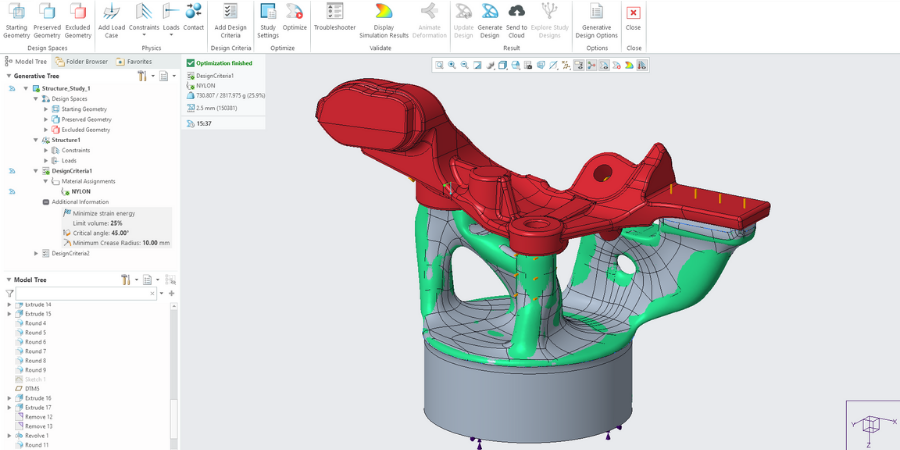
Image: A fixture (the gray/green part) created with generative design in Creo supports a cast part (in red). The technology optimizes the fixture design, taking into consideration your constraints, such as your plan to use Nylon and a 3D printer.
In this example you’ll use a desktop printer, so use the Windows 10 3D printer option on the Tray Assembly.
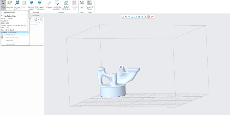
Image: Fixture placed in tray assembly.
Another alternative is to simply click File > Save as > 3MF. This generates a 3MF file with the settings you define. (Note. Almost all the 3D printer manufacturers support 3MF)
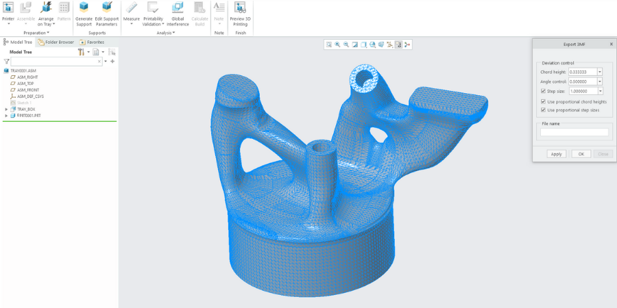
Image: Exporting the final fixture as 3MF file in Creo.
The video below walks you through a demo of the workflow for creating this Nylon fixture, including generating the model, preparing for printing, and then simulating the milling operations on the production part.
Uh oh. Your part is more popular than expected and orders are backing up. You’re going to need to rethink your production methods to keep up with ballooning orders.
Fortunately, generative design can optimize a fixture to be machined, too. Simply change your constraints so the material is aluminum (instead of Nylon), and the production method is a 3-axis milling machine (instead of 3D printing). The image below shows a generative design alternative based on these new constraints.
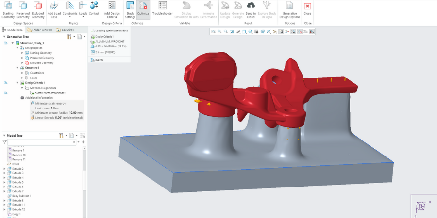
Image: A fixture (gray) created with generative design. In this case, the system optimized the fixture design for 3D-axis milling and aluminum. The cast part (red) is unchanged.
With the new machinable fixture, you can further use Creo CAM Software to create 3-axis high-speed milling toolpaths to do roughing and rest roughing.
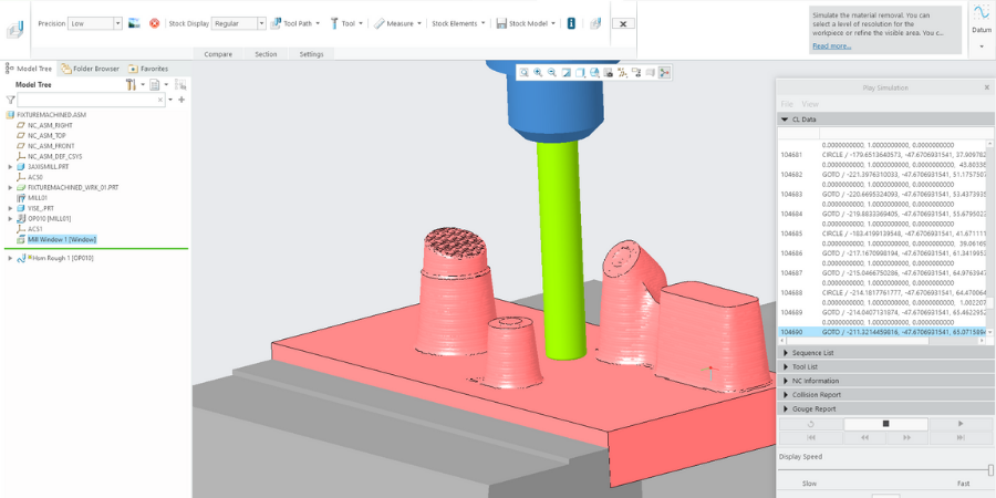
Image: Toolpath design in Creo.
With Creo every change on the original 3D model automatically propagates to the downstream processes, in this case to the manufacturing assembly for the machining operations.
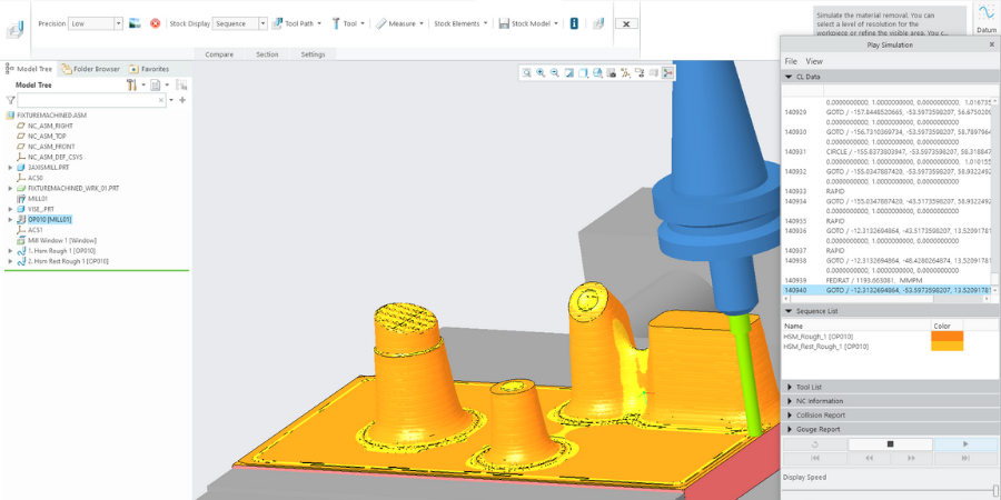
Image: Refining the toolpath in Creo.
In Creo machining extensions, like High Speed Milling Plus, you can use your generatively designed part as the reference model to define your precise milling operations.
Once the milling operations are defined, you can verify the material removal as a validation step in the process.
Those are just two solutions to our fixture design challenge. But you could choose any number of materials and manufacturing methods. Best of all, you can then apply any other Creo tool as normal to your model. Generative design promises to find the best solution no matter your constraints.
When Volvo wants to engineer the very best engine bracket, the team turns to Creo.
Watch Demo