Creo Flow Analysis and Computational Fluid Dynamics
Download the slides here.
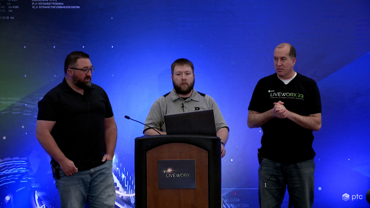
00:00 All right. Let's go ahead and get started. Thank you very much for being here, everyone. My name is Todd Craft. I'm a product manager for PTC. I work on all the simulation products at PTC. I'm going to let my other two up here also go ahead and introduce themselves. I'm Randy Stalcup. I'm an engineering systems analyst for Daktronics. I kind of head up all of our CAD tools that we have specifically on the mechanical side and kind of looking at what future technologies we have out there. I'm Ryan Cassette. I'm a mechanical design engineer with Daktronics.
00:31 I've been with the company for 15 years and ten of those I've been specializing in the thermal design of our products. All right. All right. This is going to be a great session. We have a great testimony from a customer on Creo flow analysis. I'm going to just give a quick introduction to Creo flow analysis and then I'll hand it over to Randy. So Creo flow analysis has been around for about five years, maybe six years. It really is a partnership with Cimarex. We have three different packages based advanced premium and it provides
01:03 for our customers analyst level functionality and results. Okay. Prototype level results and you can buy that in all different levels based on your complexity and needs. Just wanted to give a couple of things. In Creo nine, we made significant improvements to to to Creo flow analysis, including behavioral modeling, usability, multi-project, gyroid or hybrid geometry and a lot of post-processing improvements. You can also get unlimited support from some. Eric So take advantage of that.
01:37 And also there's also a custom training if you want it, and we do that a lot. So a lot of our customers will sign up for two four days of training and you'll get custom training for your product with some Eric's with some, you know, unbelievable CFD experts. And also for the past three years, we've been making available some webcasts we've been doing. So you can find those all on the PTC community. There's some dates there, but just look up CFD in the PTC community. You'll find all these webcasts.
02:07 There's also a how to series, and sometimes there's downloads where there's models available to to run through some of the examples yourself. Okay. So the packages that are that are available, again based on your need, if you just do heat and simulation or simulate flow and internal and external. The base package is all you need. If you start doing radiation particles or some moving meshes, then you would be in the middle tier. And then if you want, multiphase is probably the biggest reason to go to the last one
02:38 and that would be in the premium range. And lastly, what am I what are my top five reasons to buy and use Creo flow analysis? First, it's fully associative. This is full integrated CFD into Creo into PTC. Creo we have the mesher inside of CF and flow analysis is automatic body fitted to Creo even when fluid bodies rotate and slide again on the mesher it applies the physics properly automatic mesh separation.
03:10 It understands where the fluid bodies are, where the solid bodies are, connects them, makes the interfaces automatically heat thermal multiphase. It just knows how to how to solve. And then the fast solve time very efficient meshes that Creo flow analysis makes and also its prototype accuracy. And we give you up to eight cores out of the box as well. And then lastly, it paints in real time. So if you make a mistake, you have you have gravity going the wrong direction or if you have your inlets and outlets messed up,
03:41 you know right away that you have set it up wrong and you can go ahead and fix that. So with that, I'm going to hand it over to Randy and Ryan. You're going to love this. It's going to be fantastic. Ryan's going to do a live demo for you as well. So I'm going to go ahead and hand it over to them. Here you go. Randy Okay. So I'm going to do a quick video here of kind of introducing the company rather than doing a slide with a bunch of different text on it. So we're going to go ahead and do that now. Oh, hi, there we are Daktronics. We create some of the most sophisticated and iconic scoring and audio visual systems
04:13 on the planet, then ensure your projects deliver impact. We're a passionate group of designers, fabricators, project managers, sales service, digital artists, tech gurus and engineers. We're a US based company that started in a garage in Brookings, South Dakota, in 1968 with this. That's the Mat side scoreboard, one of our first products, and it changed the game literally. Today, we're a publicly traded company with thousands of employees all over the world and customers on every continent except Antarctica.
04:43 So you might be asking, you just sell scoring and audio visual systems. No, no, no, no. We do everything. We engineer design, code, test, fabricate, bend, punch, insert, paint, pack, ship install and service dynamic audio visual systems. Oh, and we also create the incredible content that goes on them. Sound like a lot. Well, we do it every day from our facilities in Brookings and Sioux Falls, South Dakota, Redwood Falls, Minnesota, Ennistymon Ireland and Shanghai, China. But you're probably thinking that all sounds great, but what have you done?
05:17 We're glad you asked. Scoreboards. Businesses large and small campuses, complex transit systems, digital billboards, massive video boards in and around venues, booming audio systems, really, really big screens. And the control systems that make them tick. They're not all just rectangles. Ever see a halo board or feather wall? How about dual hanging, three sided trapezoidal? You get the idea. They're unique. Looking to turn heads, We can even cover custom shapes or entire buildings in Led. Like I said, we do everything and we don't just build, we service everything.
05:51 We sell from installation support to troubleshooting to display maintenance and upkeep. We've got you covered 24 hours a day, seven days a week, 365 days a year. We don't only stand behind our products, we stand on them. Why do we stand on them? Because we tested it here at our state of the Art Reliability lab. We also test our stuff against a lot of other things just to see if they break. Spoiler alert they usually don't. We call that the daktronics difference, and that's why we designate millions of dollars a year for research and development. So our products are designed with the future in mind,
06:22 and you benefit from groundbreaking innovations. But most importantly, we listen to our customers and together find successful solutions for their brand and messages to deliver impact from the small projects to the large. That's what we do. We innovate, we design, and we light it up. We are daktronics. So we are the world leader in the industry and there's no doubt that you've seen our life's work from the smallest scoreboards at your local high schools to large stadiums, dynamic video displays from your convenience store message centers to large spectaculars
06:56 in areas such as Times Square, Las Vegas and Dubai. And then from small transit displays and train stations and airports to large format digital billboards that you'll see along roads and highways, we do it all. Odds are you've seen our work. And make sure you keep an eye out this week. You'll notice outside we've got a display out there on the north entrance. We've also got the display overhead here in the North lobby. And if you're fortunate enough to go over to PTC headquarters, we've also got a couple of displays in there as well. And then if you're watching the Celtics game tonight, brand new this year,
07:27 Center hung scoreboard and that facility as well. But when most people see our displays, they focus on the installation and digital content. But what many don't realize are all the design and installation considerations that we have to factor in when we develop our products and solutions. We've got structural considerations there, overhead and arenas there over the top of roadways there on the sides of buildings. We've got wind loadings to consider and a lot of national and local codes. There's environmental conditions. We've got wind, water, dust, things to worry about, their seismic conditions,
08:00 vibration when we're transporting and corrosive conditions that can erode our hardware. We've got power and signal considerations to take into account. There's sizing for electrical panels for inrush and leakage, current requirements. We've got to keep access there and keep out areas with our mechanical design teams. We've also got local and NEC codes there. We have to worry about power and signal loss degradation over long runs to our displays and heat management, which is the focus of this presentation. We've got a lot of solar load on our displays.
08:30 There's ambient temperatures to be concerned with. So if they're in areas like Dubai or in anywhere around the equator, it's a lot hotter, obviously, and electronics generate heat as well. So we've got to worry about getting that dissipated and into a workable level. And then noise, we've got not only audible sound, but we have to worry about electromagnetic interference. And then if we have to place a display somewhere, we've got to consider proximity to radio and cell towers and other wireless equipment so that we don't knock out different emergency services and stuff.
09:01 So there's a lot to be considered there. So today we're going to focus on heat management in our products. And traditionally, Daktronics has struggled to find a reliable CFD analysis tool when it comes to airflow and heat management Within our display Chassies. We do a lot of prototyping and testing, but as we know, prototypes can be expensive and they take take some time to manufacture. And then oftentimes we've got multiple rounds of prototyping that are needed to redesign based off of product testing results . So you have that loop there.
09:32 Ideally, we would like to simulate some of this airflow and heat dissipation within our cabinets. And so we originally were using Autodesk CFD for our digital prototyping, but it was tough to get our tough to learn. It was a difficult learning curve with it and we couldn't get reliable results that match our real world testing. So it then loses a little bit of confidence for our designers. And then they don't use the tool unless use equals knowledge lost and the cycle just starts over. So we began looking for other options. So we were introduced to Cimarex in early 2018 through our CAD account manager here
10:04 for PTC told them we were looking for alternatives to Autodesk CFDs. So Rich Moore and Lacie from Cimarex flew from South our flew to South Dakota to show us what Cimarex MP was capable of at the time. They were demoing this tool as an add on our tool kit, add on for Creo parametric and they were hoping that we would like it. So the story they pitched went like this. Designers and engineers are intimately familiar with their products and their designs, but don't have much knowledge with using high end CFD analysis software. Similarly, there's a ton of analysts out,
10:35 not a lot of analysts out there, and they don't know the CAD tools very well. And so traditionally, there aren't as many analysts as well as designers. So there's a little bit of a gap there. So designers typically only had some low end CFD tools that can help with guidance, but not necessarily helping them make design decisions. And alternatively, the analysts had a high end CFD tool that are highly accurate, but usually have to be done outside of CAD tools completely, which kind of creates this gap that Rich calls the CFD void, I guess.
11:07 And this void is where Marek said that they were working on some kind of a solution. A custom version of Summercamp, not the standalone version. Could be a high end solver that works directly with our models. And the idea there was to take the power of traditional CFD tools, get it into the hands of the mechanical designers early in that design process to help with our digital prototyping. So early on, we liked what we saw. It was a much improved UI. It was easy to understand and we were able to work right within our Creo model.
11:37 What they were showing us was limited in terms of capabilities. That was a work in progress at the time. And while they were doing this analysis in our cabinets, we encountered some problems with meshing on such a large digital volume and with the amount of sharp edges that we have around the cutout. So you can kind of see on the top and bottom of that display. But inevitably we did like what we saw and we asked them if they could be improved upon and see if it could be a viable solution for Daktronics if they could get this tool to us fully integrated with a full set of capabilities and we can get accurate results that match our digital prototyping
12:09 or match our physical prototyping, this will be a home run. So we challenged them to work on this and left them with a little bit of homework. So Lacy from Cimarex went to solving that problem and continued working with us through the fall and winter of 2018. Just after that, though, in February of 2019, I was asked to participate on a Creo simulation live webinar here at the headquarters for PTC, and we discussed the usage of this nicely embedded tool and what kind of an impact a tool such as this could mean in
12:41 the hands of our designers. But while on this trip, I was also informed that there were two other high end solvers that were being added into Creo Parametric. We had the Ansys working on a project, a product to get a high end structural analysis tool there, which is now Creo Ansys simulation. And we also found out that Cimarex is working on a high end CFD tool that was being introduced into Creo. So while on that trip, we had a call back with Rich from Cimarex and we discovered that even before Samir was working with Daktronics,
13:11 Rich and Mark Fisher with PTC, had already been begun discussions regarding a fully integrated CFD tool within Creo Parametric. Essentially, the pitch was the same as what Rich presented to Daktronics. They just took it a step further and instead of being a cimarex tool add on, they now called it Creo flow analysis. Excuse me. Even better, many of the improvements and requests that we had from Daktronics were put into this new software around the sharp edges and the small volumes, and it truly is a true partnership.
13:43 Cimarex now has full access to all the APIs that Creo developers have. They then continue to update and improve the physics in the meshing of the automated automatic body fitted to the Creo models, and developers will then work on improving the overall UI to be able to apply loads of constraints right into the Creo models. Creo flow analysis is fast to simulate and accurately match hardware prototypes and reduces prototype iterations. So after that, Rich felt it would be in our best interest to,
14:16 instead of going down the toolkit path to go down the Creo flow analysis path. So some of the benefits that we're seeing from Creole flow include the need for fewer physical prototypes. As we learned during Covid. This is a great tool to have. Like many companies, we had limited access to our factories and for our physical prototyping efforts. Something digitally that had accurate results was a very big benefit for us. It was very easy to use. Designers are able to apply loads right within our Creole models and the UI is familiar. We've got greater confidence in this tool.
14:47 We get better results. It's used now more often. The body fitted. Meshing is really unmatched in the industry and design iterations can be done easily. If there are changes, there's no remodeling necessary for tools outside of Creo parametric. We've also got improved painting. We now have the ability to show non-technical people what the air movement and heat dissipation is doing within our digital prototype, and so that helps them make some design decisions and we've got incredible support. PTC focuses on the UI. Cimarex keeps focusing on the tool to keep it state of
15:18 the art and any issues that we experience along the way. Cimarex has done a great job of replying to those and getting fixes in almost immediately. So with that, I'm going to turn it over to Ryan and he's going to walk through the ways that we're using it in a firsthand sense. All right. All right. Thanks, Randy. I'm Ryan Burkhardt, mechanical design engineer with Daktronics. I spend about 30 hours of my design time in Creole flow every couple months,
15:49 so every 8 to 9 months. And that's our development cycle. So there is no way that I am a design analyst per se, but I would be considered a power user at Daktronics. So my goal here is to show you the benefits from Creo flow that we liked at Daktronics and some other top features that may find others helpful. So native CAD is a big deal. We like to be able to use the same models, same user interface, not have to do a bunch of converting and whatnot.
16:19 We use a lot of conjugate heat transfer at daktronics. The PCB designers give us our heat loads for a total heat source on our components and then we also have outdoor displays. So we have to count for some type of solar radiation in that type of analysis. When we get to the flow portion of it, we use porous materials to simulate cabinet impedance, try to get better flow and see where we can improve. And then we use our fan curves supplied by our fan manufacturers. And then lastly, get into some live results. The quick solver is great.
16:52 It's easy to update on the fly and you'll see that in the live demo. So native CAD. Previously we used Autodesk CFD simulation. Creo file extensions are not easily imported into Autodesk. We had to export into a step file or a generic file and then import. And a lot of times you'd lose material. We would lose accuracy unit mismatch. All of this would lead to some type of collision or overlapping in the models and usually not easily identified during setup.
17:23 So during boundary condition assignments, material assignments, etcetera, we wouldn't necessarily find these errors until we went to mesh and then it would mesh with failure or mesh without failure if the guess what it was. Or they'll just tell you there's overlapping entities and you'd have to go back to Creo, fix the overlapping and find the identified areas. Re Outport re set up a lot of loopback and as a result there's no live feedback, no results given right away. So once it was meshed and was running running,
17:56 we wouldn't know if there was any flow direction, error or if there is reverse gravity in a natural convection flow analysis or any mis boundary conditions. And at this point in the time we were using it, it was a click start, go home for the day, come back only to find that, oh, I had the fan direction wrong. So the analysis was essentially useless. This is just a couple of pictures of native CAD. So the bottom left is all in-house design, creo parametric parts. And then we use a simplified model when we do our CFD stuff on the front end.
18:29 Conjugate heat transfer. So 95% of the simulations we do at Daktronics include some type of conjugate heat transfer and air flow analysis. So heat flow management of all the electrical components is critical for image quality and reliability. We want to sell a ten year product and we want it to look great over that ten years. As components heat up, they degrade over time. So that is the the number one type of analysis we're doing. Daktronics has indoor and outdoor displays,
18:59 so we have to account for both an indoor condition and an outdoor condition. We prefer natural convection cooling in indoor applications because they're quiet. It's low maintenance. People aren't going to be bothered by the noise. ET cetera. But for the outside outdoor environment, we need forced air cooling. Typically, there's just a larger heat load with the displays, the solar loading, the ambient temperature that's always adjusting. And of course, we go into all environments in the world,
19:29 so we have to account for that. Just some indoor verification stuff. We do still use benchtop testing to verify the critical component temperature. Make sure our boundary conditions match or as expected. But again, this is kind of a progression. We use PCA assemblies, we simplify using simplified reps, we do our conjugate heat transfer analysis on it and then verify with an image or some type of testing. Outdoor verification is very similar. We verify outdoor solar radiation using some of our in-house test chambers,
20:01 but essentially we really like the versatility of the Creole flow that allows us to use both indoor and outdoor cooling methods, full analysis portion of it. So Daktronics uses a lot of fan curves for our chassis, airflow, ventilation. In case you're not familiar, fan curves provide the airflow versus pressure for a given fan. Creole flow allows us to use a text file and read in those characteristic curves and apply them directly to the components being used in the analysis.
20:32 So we take our supplier curves, we convert them into a text file and put them in the working directory. That allows us to quickly change between fans that we may use in some type of system. System impedance curves is the internal pressure inside of the system versus the airflow. Ultimately, the goal is to provide the best fan curve versus system impedance to meet our operating point. So on the left is our system curve. The middle are two different fan curves and we're looking for the optimum operating point more on the system impedance,
21:06 obviously porous materials is what we use to simulate and use that as an easier tool to account for blockages or any restrictions that might happen in the system. So in our outdoor displays, we worry. We use filters for our outdoor displays, we use some type of perforated material at the intake and it's varying depending on customer wants and needs. Esthetics can be important. So what we do is we use a porous material property in career flow to simulate all of
21:36 these. We take an open area requirement and and use our filters and we use it as a porosity scale. So one being fully closed and zero being open and you can vary that and find that optimum point. And then live results. So various design simulations can be quickly compared and designed and run through and the best candidates are moved forward. So up in the upper left you have a higher flow of fan. The bottom mid is a different fan in our configuration, providing a different airflow,
22:10 but the same setup. Those can be quickly viewed and moved forward, which we prefer. Whatever design meets our targets. And then the upper right, it easily is changed to account for a different fan configuration. So it's very quickly, very easy to use. Okay, here is the Creole full model. You can see it. So this is the picture I had in the slideshow. It's just a fan with a PCB material mounted in there and then an aluminum enclosure
22:43 and a porous material for an intake for the model setup. There's a few different ways to do it. A project you can use, the wizard, the built in wizard, or you can use each step and pick your modules you want to do. But for this, we're going to do The Wizard. So we want to name our project. And we want to do a flow module with some turbulence, heat transfer,
23:17 and then we'll use some streamlines to see where the airflow is going. We're doing a forced error analysis, so we do not need to specify gravity, but we can come back and add it later. Yes, I would like to create my fluid flow domains for a heat conjugate heat transfer. We have to use both. And here I am selecting a bounding box for the analysis. I want a non uniform box. I want it on the floor. Actually, we'll raise it above the floor.
23:51 Mounted on a wall and then we'll give it some air to breathe. Next. Oops. We want to add some fluid domains. So it already had added the mesh that we created for the boundary box. We are going to leave it as a constant density because we're not doing a natural convection, but you can come in here and change your density based on different types of analysis. But we do need to add a couple more. So the fan.
24:24 Five minutes fan. Blades need to be defined as an air volume to properly put the fan curves on them. Apply the fan curves and then the porous material we use as an air volume. We want the solid domain so we know where the heat transfer goes. We want to contain the airflow in the box. We need to have a solid housing for the fan and our heat generating components.
24:54 I'm right here. It gives you a live feedback of the material selection. So if we wanted to determine what copper would do on a heat sink or some type of other material, you can easily go in here and change it. I'm going to leave these as is for now. We're not going to do any inlet boundaries. I don't have any outlet boundaries. I don't have any other surface boundaries, and I'm not going to set any volume parameters. This is another one where you can go in later, add them as as you want. I'll show you that. But now we're setting up the actual analysis.
25:27 So this is a steady state. We want it to run 500 iterations. Daktronics uses a standard mesh, so there is an adjustment for the cell size, the minimum cell size, that type of thing. But as not an analyst and I don't have any super concerns, I'm not going to concentrate in any areas, so I'm going to leave it as the defaults. So we're going to generate the mesh.
26:04 One second, adding the mesh to the geometry. And then here we can select some outputs from our analysis. So I'm interested in some temperatures and I'm specifically interested in a volume. Of this these three components here. And I want to know what their temperature is. So you go in here and you can click your temperature and I want these on a new plot. I want to plot them against each other to see how they compare. So this is automatically setting up our outputs.
26:35 I'm not ready to run the simulation yet. I haven't assigned any conditions. So no, a couple of things I will do as best practices is to check the the meshing. Of our domains. Specifically the small components that you are most interested in. So this shows us the mesh. And you can see that his mesh properly. I do want to set up a condition for a new heat source.
27:07 Which is a total heat source and we would want to dissipate one watt per each component. So they are now set up to dissipate heat. I want to set my poorest material at a at our porosity value of 50% . But you can come back and change that later. Now I'm going to go into the boundary conditions. I'm going to set up.
27:42 Zoom out here so you can see what I'm doing. I'm going to set up the external pressures. These are going to be pressure inlets and this is the floor. Then we go into our interface and we set up our fan curve to set up a fan curve. We assign it to the interface between the two fan blades.
28:13 So I need to find that here. This is the fan direction. I want to set this up as a fan model. And let's say the flow direction is in the Z direction to show you the live results. And then I need to set up my fan curve so my fan. Was equal to table.
28:45 And I've done this enough to practice for this that I know what it's named. But if you need to revert back, you can. And I want to sign this. The fan. So now we are ready to go ahead and solve. So we want to turn on the x y panel and click run. And it is running.
29:17 Well, as you can see, that nothing's happening. So you can see something is wrong. Oh, my temperature is spiking. I forgot to turn on the stream lines if I'm interested in the air. So let's pause it. Stop close. I am interested in this porous material. I want my particles to go so I know where my problem is in my setup. Both run.
29:48 Turn on my stream lines. And let's see. I want the flow velocity. And you can see here something is not working. So live on the fly. Problem solving is one of the benefits and features I had shown in the previous slides.
30:20 So you can see here that I'm not getting any velocity. So that tells me my fans not working. So either I pick the wrong direction or my fan definition is wrong, but it's live. I figured it out in two minutes or 30s or whatever it took here, so stop. Let me look at my fan material. I fan blades. Whoops. Oh, yeah. I have it set in the wrong direction. I want it to go in the positive y direction.
31:00 And now my stream lines are working. And I have some volumetric flow. Pick your planes.
31:33 So, yeah, that's the live demo. Your time is up. There are any questions? Time for questions. All right. Any questions at all from in the audience? We can also take it outside as well. Ryan. I'll figure it out. There you go. Yeah. Say is going. I just take some time. Okay. Yeah, we are over time, but thank you very much. Thanks, Ryan. Thanks. Thanks, Randy. Fantastic session. Yeah.